
As electrical loads expand, protection equipment must handle more current, heat, and operational stress. The International Energy Agency’s Electricity 2024 report projects global electricity demand to grow by an average of 3.4% annually through 2026. That growth affects factories, data centers, commercial buildings, and renewable-energy facilities. In these environments, an Air Breaker can provide dependable circuit protection, switching, and isolation for high-current distribution systems.
An Air Breaker interrupts faults through air rather than oil or other insulating media. Modern air circuit breakers commonly support adjustable long-time, short-time, instantaneous, and ground-fault protection. These functions help engineers coordinate upstream and downstream devices more accurately. IEC 60947-2 provides the key performance framework for low-voltage circuit breakers. UL 489 also guides breaker construction and testing in North American installations. A draw-out design can simplify inspection, testing, and replacement. That matters when a production line cannot tolerate lengthy shutdowns.
Field commissioning often reveals the difference between a suitable breaker and an oversized purchase. A technician may need to test trip settings beside a warm switchboard, not merely read a catalog rating. The breaker must match the system voltage, continuous current, interrupting capacity, bus arrangement, and coordination study. Protection matters. The choice is not automatic. A poorly selected Air Breaker may create nuisance trips, inadequate fault protection, or unnecessary capital costs. This guide examines where air breakers deliver practical value, where their limitations deserve attention, and how reliable selection supports safer, more maintainable electrical projects. Mistakes remain possible, even with excellent equipment.
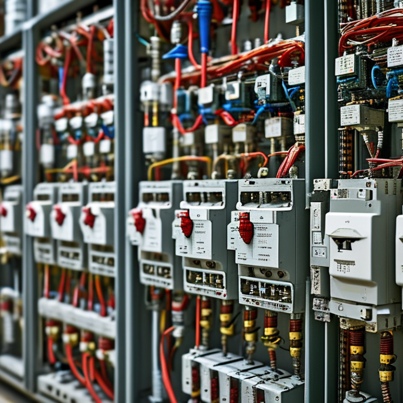
An air breaker, often called an air circuit breaker, protects electrical systems from dangerous current conditions. It uses ordinary air to extinguish the arc created when its contacts separate. When a circuit experiences overload or short circuit, the trip unit detects the abnormal current. It then releases the operating mechanism. The contacts open quickly inside an arc chamber. Splitter plates divide and cool the arc until current flow stops. No special insulating gas is required.
In practical switchboard inspections, technicians check contact wear, insulation condition, spring mechanisms, and trip settings. These details matter more than appearance. An air breaker may also include adjustable protection for long-time, short-time, instantaneous, and ground-fault conditions. Proper adjustment should match the cable rating and expected load. A setting that is too high can delay protection. One that is too low may cause unnecessary interruptions.
Air breakers suit large low-voltage distribution panels where frequent switching and clear maintenance access are important. Their visible construction can help technicians diagnose problems, but visibility does not replace testing. Dust, loose connections, and moisture can reduce reliability. I would not select one by current rating alone. Available fault current, enclosure space, coordination, and service conditions also deserve review. A small oversight here can become expensive. Periodic testing by qualified personnel provides stronger assurance than assumptions based on a new-looking device.

Why Choose an Air Breaker for Your Project?
Air breaker performance begins with interrupting capacity. IEC 60947-2 defines Icu and Ics in kiloamps, showing how safely a breaker handles fault current. Ics matters during operation because it indicates service continuity after interruption. A practical selection should compare both values with the installation’s prospective short-circuit current. Bigger is not automatically better.
Trip accuracy also shapes protection quality. Modern electronic trip units monitor long-time, short-time, instantaneous, and ground-fault conditions. Adjustable settings support coordination between upstream and downstream devices. NFPA 70, 2023, emphasizes properly rated overcurrent protection and selective coordination in critical systems. A poorly adjusted trip unit can defeat an otherwise excellent design. Small detail.
Arc chutes, contact wear, and operating mechanisms influence reliability over time. IEC 60947-2 includes endurance classifications, helping engineers assess repeated switching duty. The IEA’s Electricity 2024 report forecasts global electricity demand growth of about 4% in 2024, increasing pressure on distribution equipment. In field inspections, heat marks, loose terminals, and slow mechanisms often reveal neglected maintenance. Thermal imaging can expose abnormal temperature rise before failure, although it cannot replace torque checks or functional testing. Designers should review altitude, ambient temperature, enclosure ventilation, and available maintenance space. I would not specify an air breaker from current rating alone. Fault level, coordination, environment, and lifecycle testing must agree.
Air breakers suit different project requirements because they offer flexible protection for low-voltage power systems. They interrupt fault current through air, without relying on oil or special insulating liquids. This design supports cleaner equipment rooms and simpler routine inspections. It also allows engineers to select thermal, magnetic, or electronic trip settings. Each option responds differently to overloads and short circuits. That flexibility matters in factories, commercial buildings, data centers, and infrastructure projects.
Project conditions should guide the selection. A facility with large motors may need adjustable short-circuit protection and careful coordination between breakers. A compact building may value clear status indicators and easy access for testing. In dusty or humid locations, the enclosure and installation environment require closer review. Air breakers can provide strong performance, but only when their interrupting rating matches the available fault current. This detail is easy to overlook. It should not be.
Maintenance requirements also influence the decision. Technicians can inspect connections, mechanisms, and trip units without handling liquid insulation. Regular testing still matters, especially after heavy faults or long idle periods. Engineers should check temperature rise, conductor sizing, breaking capacity, and selectivity before approval. Sometimes, a smaller protective device appears cheaper. That choice may increase downtime later. Air breakers are not automatically the best answer, but their adjustable protection and serviceable construction can fit demanding projects when the design is properly verified.
Why Choose an Air Breaker for Your Project?
How to Select the Right Air Breaker for Your System
Selecting the right air breaker starts with the system, not the catalog. Define operating voltage, continuous load, fault level, and switching duty. A breaker rated only for normal current may fail during a short circuit. Check the available short-circuit current at the installation point. This value guides the required interrupting capacity. Leave engineering margin.
Next, match the frame size and trip unit to the real load profile. Motors, transformers, and capacitors create different starting or inrush currents. An adjustable trip unit can prevent nuisance trips, but settings must protect cables and equipment. Choose the number of poles carefully, especially where neutral switching or ground-fault protection is required. Review voltage, frequency, insulation level, and ambient temperature together. High temperatures reduce usable capacity. They matter. For dusty or humid rooms, select a suitable enclosure and maintenance arrangement.
Installation conditions can change the decision. Measure panel space, busbar alignment, cable entry, and access for testing. A compact breaker is not automatically better. Technicians need room to inspect contacts, operate the mechanism, and verify trip functions safely. Confirm compliance with applicable electrical standards and coordination studies. Protective devices should clear faults selectively, so one upstream breaker does not shut down an entire facility. Ask for tested data, service procedures, and clear trip curves. Future load growth is easy to overlook. I would not size blindly for expansion, but ignoring it may force an expensive replacement. Recheck the design after real load measurements, because paper assumptions are sometimes wrong.
| Selection Dimension | Typical Data or Options | Selection Guidance | Why It Matters |
|---|---|---|---|
| Application | Main incoming feeder, bus-coupler, generator connection, large motor feeder, or industrial distribution board | Use an air circuit breaker when the system requires high continuous current, adjustable protection, frequent operation, or coordinated low-voltage distribution protection. | Air breakers provide accessible settings, serviceable construction, and protection functions suitable for major low-voltage circuits. |
| System Voltage | Common low-voltage ratings include 400 V, 415 V, 480 V, and 690 V AC | Select a breaker with a rated operational voltage equal to or higher than the system voltage. Confirm the applicable local standard and insulation requirements. | The voltage rating determines whether the breaker can safely interrupt and withstand the system voltage. |
| Number of Poles | 3-pole or 4-pole construction | Use 3-pole units for three-phase systems where the neutral does not need switching. Use 4-pole units when neutral isolation or neutral protection is required by the system design. | The pole arrangement affects isolation, neutral management, transfer schemes, and maintenance safety. |
| Rated Continuous Current | Typical project range: 630 A to 6,300 A | Choose a frame and sensor rating above the calculated design current while considering ambient temperature, enclosure conditions, conductor ampacity, and future load growth. | Adequate current capacity prevents overheating and nuisance operation during normal loading. |
| Short-Circuit Breaking Capacity | Common interrupting ratings: 42 kA, 50 kA, 65 kA, or 100 kA at the specified voltage | Calculate the prospective short-circuit current at the installation point and select an interrupting capacity equal to or greater than that value. | The breaker must safely interrupt the highest fault current available from transformers, generators, utility supplies, and parallel sources. |
| Short-Time Withstand Current | Typical values include 25 kA to 85 kA for 1 second, depending on the design | Check the required short-time withstand current and duration when using selective coordination or maintaining a delayed trip for downstream faults. | A suitable withstand rating allows upstream and downstream breakers to coordinate without premature tripping. |
| Trip Unit Functions | Long-time, short-time, instantaneous, and ground-fault protection | Select adjustable electronic protection when load characteristics, coordination requirements, or generator operation require flexible settings. | Adjustable trip functions improve protection selectivity and help match the breaker to cables, transformers, motors, and busbars. |
| Protection Setting Range | Long-time pickup commonly adjustable from approximately 0.4 to 1.0 times the sensor rating | Set the long-time pickup below the allowable ampacity of the protected conductors and above the expected continuous operating current. | Correct settings reduce nuisance trips while protecting conductors and equipment from sustained overloads. |
| Installation Type | Fixed, draw-out, or plug-in arrangement | Choose fixed installation for compact, stable equipment. Choose draw-out construction where rapid inspection, testing, replacement, or maintenance isolation is important. | The installation type affects downtime, maintenance access, safety procedures, and switchboard layout. |
| Operating Mechanism | Manual, motor-operated, shunt-trip, undervoltage-release, or electrically closed operation | Use motor operation and remote accessories for automatic transfer, energy management, generator paralleling, or remote switching applications. | The operating mechanism determines how quickly and remotely the breaker can open, close, or be controlled. |
| Coordination Requirement | Selective coordination, cascading, or energy-reducing maintenance switching | Review time-current curves, breaker settings, available fault current, and upstream/downstream device characteristics as one protection system. | Proper coordination limits unnecessary power interruptions and helps isolate faults to the smallest practical section. |
| Environmental Conditions | Indoor or outdoor installation; temperature, altitude, humidity, dust, and corrosive atmosphere | Apply manufacturer derating information for high ambient temperature or altitude, and specify the appropriate enclosure and ingress protection for the location. | Environmental conditions can reduce current capacity, insulation performance, mechanical life, and reliable operation. |
| Standards and Certification | IEC 60947-2 or the applicable national low-voltage circuit-breaker standard | Verify rated voltage, current, breaking capacity, utilization category, temperature rise, dielectric performance, and test documentation against the project specification. | Standards provide a consistent basis for safety, performance testing, installation approval, and equipment comparison. |
| Maintenance and Lifecycle | Inspection access, replaceable accessories, trip-unit testing, and mechanical/electrical endurance | Consider the operating frequency, service personnel requirements, spare parts, test equipment, and planned maintenance intervals before final selection. | Lifecycle planning can reduce downtime and total ownership cost over the service life of the distribution system. |
Typical values are provided for preliminary project comparison only. Final air-breaker selection must be verified against the calculated load current, prospective short-circuit current, conductor ampacity, coordination study, environmental conditions, and applicable installation standards.
Why Choose an Air Breaker for Your Project?
Installation, Maintenance, and Safety Considerations
An air breaker suits projects needing reliable protection for large electrical systems. Its open-air arc interruption design allows inspection and servicing without sealed gas equipment. Installation starts with a verified load calculation and correct interrupting rating. The enclosure needs clear working space, firm mounting, and suitable ventilation. Cable lugs must match the conductor size. Tighten every connection to the manufacturer’s specified torque.
Do not rush this step. A loose termination can create heat, discoloration, and eventual failure. A qualified electrical professional should test insulation, protective settings, and mechanical operation before energizing the breaker. Local electrical codes and the project’s arc-flash assessment must guide the work. One detail is easy to miss: confirm that the breaker fits the busbar alignment after final mounting, not only during the first inspection.
Maintenance should be planned, not reactive. Isolate the supply, apply lockout procedures, and verify the absence of voltage. Inspect contacts, terminals, springs, trip mechanisms, and arc chutes for wear or contamination. Remove dust carefully, then test trip functions according to the service schedule. Infrared scanning can reveal abnormal heating during operation. Keep dated records of readings and replaced parts. A checklist helps, but it cannot replace judgment. If a mechanism feels stiff, stop and investigate. Never bypass an interlock or work near exposed conductors without approved protective equipment. Safety depends on disciplined habits.
Copyright ©2024 Elephant Lifting Products | All rights reserved.
38381 N Robert Wilson Rd, Gonzales, LA 70737 USA
Toll Free: (888) 844-6113 | Phone: (225) 644-6113 | Fax: (225) 644-6695
Email: sale@floralift.org